Over the last couple of decades the use of rechargeable batteries has grown enormously, and for most common applications there are ASIC
1
s which control battery management with very little additional circuitry. In the last few weeks, however, I have encountered two issues where non-standard solutions are useful, and in each case a less well known feature
2
of many voltage references complicated the design. The issues are the measurement of battery capacity, and the charging of a lead-acid battery from a solar panel with minimal power dissipation in the control circuitry.
I built both of these at the same time, and when I tested the first prototypes the hysteresis of the comparators was much greater than it was designed to be. The circuit used is shown in Fig 1 and consists of an ADR291 or ADR292 voltage reference driving the non-inverting input of an AD822 or an AD8667 op-amp through a small resistor, R
in. The output of the op-amp goes to this input via a large resistor, R
fb, to provide hysteresis. There is a 1N4148 diode in series with R
fb - this ensures an accurate threshold as the voltage on the inverting input goes low since feedback current flows through R
fb only when the op-amp output is greater than the reference voltage and the diode is conducting. The hysteresis of this circuit is R
in(V+ - V
ref - V
diode)/(R
in + R
fb) where V+ is the op-amp positive supply voltage and V
diode is the voltage drop in the 1N4148 diode.
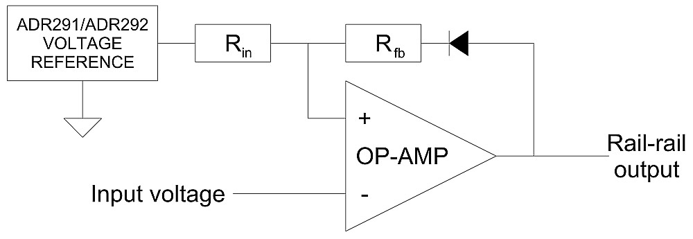
Fig 1. Simple threshold circuit - which does not work with some references!
When I designed this circuit I assumed that if I used 1MΩ as R
fb the current (approx 10μA) flowing into the reference output would flow in the resistor chain R1 + R2 + R3 (see the simplified schematic of these references in Fig 2 below) and the reference accuracy would be unaffected. In fact measurements on a number of ADR292 devices show that they will not tolerate reverse currents above about 5μA without their output voltage rising by about 40%. This caused me to abandon my original design and to write this article. The final designs are described below.
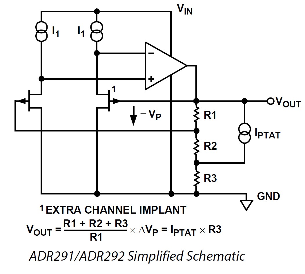
Fig 2. AD291/2 Simplified Schematic
Of course if I had used a voltage reference with an output stage capable of sinking as well as sourcing current there would have been no problem.
Rechargeable Battery Capacity Measurement
The measurement of battery capacity has become important because of blatant overstatement of battery capacities by manufacturers and retailers. I recently needed to power an item of medical electronics (a CPAP machine) for three days without access to an electricity supply. Calculation suggested that three 18650 Li-Ion cells with 3AH capacity would do this, but when I bought three with alleged capacity of 3.6AH from a well-known retailer and tested them they lasted less than one day. At about the same time my sister complained to me that the battery life of her cordless phone had dropped over five years from seven days to two, but that when she had replaced its pair of 800mAH NiMH AAA cells with new ones bought from the shop that had sold her the phone the life with the new batteries had further dropped to little over a day.
Some experiments seemed a good idea. Several battery chargers have battery capacity measurement as a feature but when I used one the results from consecutive tests of the same battery varied by more than 25%. It was at this point that I built the battery capacity measurement circuit shown in Fig 3.
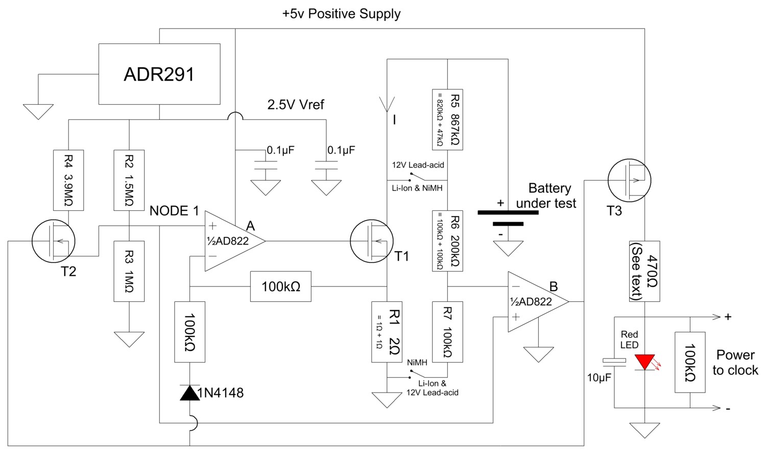
Fig 3. Battery capacity measurement circuit
My original intention had been to build a smart charger with integral capacity measurement. But I already had a smart charger which worked very well as a charger. If I had built my own I would have had to build quite complex circuitry and write Arduino (or some other microcontroller - but I talk Arduino already) software to read battery voltages and display them on a digital display. If I simply made a circuit which powered a clock while discharging a fully-charged battery at constant current, and stopped the clock (and the discharge current
3
) when the battery was fully discharged, then the product of the current and the discharge time is the battery capacity (at the particular discharge current used).
Such a system requires merely a cheap analog quartz clock, a constant current sink and a threshold switch to turn off the clock when the battery is discharged. The circuit in Fig 3 is fairly obvious - the ADR291 voltage reference and R2 & R3 provide 1V at node 1 when the battery is charged. This voltage is the voltage reference for a constant current sink comprising op-amp A, T1 and R1. The bias current of an AD822 is sufficiently small that its loading of the voltage divider is insignificant.
For my purposes (2400-4000mAH Li-Ion cells) 500mA was a suitable discharge current but larger cells may need higher currents and smaller ones less. Somewhere between the 4-hour and the 10-hour rate is usually suitable for measuring and comparing capacities. T1 and T2 need low threshold voltages
4
(<1.4V) and T1 and R1 must dissipate whatever power is necessary to handle the highest expected current. The voltage across R1 is always 1V during discharge and the current is adjusted by setting R1:-
I = 1V/R1 Eq 1
The dissipation in the resistor is therefore:-
V2/R1 = 1/R1 W Eq 2
The dissipation in the transistor is the product of the current and the maximum voltage across it, V
bat. Maximum transistor dissipation is therefore:-
(Vbat - 1V)((1V)2/R1) W Eq 3
V
bat is 14.2V for a 12V lead-acid battery, 4.2V for a Li-Ion cell, and 1.4V for a NiMH cell and the minimum voltages, for fully discharged batteries, are respectively 11.67V, 3.0V and 1.0V.
The prototype used two NXP PSMN9R0-25YLC MOSFETs, which were definitely overkill on current rating (46A!) but I had some in my junk box and the ones I measured had suitably low threshold voltages (~1.2V) and off-state drain leakage (<<1μA). Since in addition to small NiMH calls and ~3AH Li-Ion cells I expected to measure small 12V lead-acid batteries (up to 10-12 AH) at discharge currents up to 1A T1 was mounted on a heat sink capable of handling 20W. Most users of this circuit will not need such high dissipation.
The battery voltage sensor consists of op-amp B used as a comparator and resistors R5, R6 and R7, variously switched depending on the battery being measured, which present exactly 1V to its inverting input when "fully discharged". While the comparator is waiting for the battery voltage to drop to this value the reference voltage is 1V and the output is at the negative rail, turning on PMOSFET T3 to power the LED and the clock, and turning off T2.
All the numbered resistors should be 1% parts, in which case no further adjustment of the circuit will be necessary. All the values needed are single E12 resistor values or two E12 values in series (R1 & R5).
When the battery drops below the "fully discharged" threshold op-amp B output moves towards the positive rail, turning off T3, the LED, and the clock; and turning on NMOSFET T2 to bring R4 into circuit, raising the reference voltage at node 1 to 1.2V, turning off the discharge current by biasing the inverting input of op-amp A, and latching op-amp B high until the battery voltage rises above 1.2 times the "fully discharged" value.
This normally happens when another fully-charged battery is inserted to make another measurement.
My original plan, as I have said, was to use an Arduino and a small display to handle these functions and display the discharge time, but I realised that it is possible to buy an analog quartz clock for 99¢ in a Dollar Shop
5
which is designed to work with a 1.5V battery but will happily run from a 10μF capacitor across a working red LED (red LEDs light at ~1.7-1.9V and the clock movement tolerates this easily but other colours of LED have higher working voltages and should not be used - the 10μF capacitor is necessary to provide the pulse current when the quartz movement steps). If the clock is reset to 12:00 before each test it will run while the battery is discharging and stop when the "fully discharged" voltage is detected, displaying the discharge time.
The product of the discharge current and the discharge time is the battery capacity (strictly the capacity at that particular discharge current).
Since building this gadget I have tested every secondary battery in the house, and am appalled at the difference between the claimed performance printed on the battery and the actual measured capacity. This applies to batteries from reputable retailers, not just market stalls and dubious dealers on eBay. The majority of 18650 Li-Ion cells that I have measured had less than 40% of their advertised capacity, and some NiMH AAA cells, like the ones my sister bought for her cordless phone, had capacity of under 150mAH against an advertised value of 800mAH - less than 20%! Only batteries from electronic distributors have (generally, but not invariably) the capacity they purport to have.
Caveat emptor
6
! And build this gadget and test 'em.
Solar Photovoltaic Charger for a Lead-acid Battery
At the end of my garden is my woodshed. It would be difficult to connect it to the mains electricity supply, but sometimes we run out of wood at night
7
, so some lighting is desirable. For several years we had a cannibalised (mains power removed and replaced by a resistor to enable operation from 12-14V) LED spotlight powered by eight primary D-cells which were replaced every year or two, but recently I replaced the 12V 7AH lead-acid starter battery from the lawnmower just as my neighbour retired a damaged solar panel from his boat and offered it to me for parts.
It seemed sensible to replace the existing power supply with the scruffy old battery and keep it charged with the scruffy old solar panel. The only problem was that the solar panel charge controller was [A] broken (sea water had caused a short-circuit and various burnt components), and [B] designed for a 110AH battery rather than a 7AH one.
Float charging of a lead-acid battery requires very precise voltage control and temperature compensation. Too high, or too low, float voltages damage the battery in the long term. It seems to me that there is a simpler technique for a battery which, even when old and damaged, has much more capacity than is needed for occasional 6 minutes bursts of 150-200mA.
Float charging from a solar panel either requires quite a complex switching regulator, or a linear current limiter which will dissipate several watts in bright sunshine, but simply connecting the solar panel (maximum current at midsummer noon approximately 800mA) to the battery through a diode and a MOSFET switch charges the battery effectively without any components dissipating significant heat. The solar cell and the insolation define the charge current without further electronics.
When the battery voltage exceeds 13.8V the battery voltage sensor (op-amp A) turns off the switch and allow the solar panel to go to full voltage (but no current) until the battery voltage drops below 13.4V when the cycle is repeated. Although this is not the best possible charging regime it is less damaging to the battery than ill-adjusted float charging, very simple to implement, and has minimal component power dissipation and no need of any heat sinks.
The circuit is shown in Fig 4. In this case op-amp A does act as a comparator with hysteresis, similar to the one in Fig 1 but without the diode, but R3 and R4 draw 20μA from the ADR292 output, so that when the comparator output is high and approximately 6μA flows into the ADR292 from R6 its net reference current is still out rather than in and so there is no loss of accuracy.
As in the previous circuit the numbered resistors, R1-R6, must be 1% to eliminate the need for any other adjustments to the circuit. All are E12 values, except R1, which consists of two E12 resistors in series.
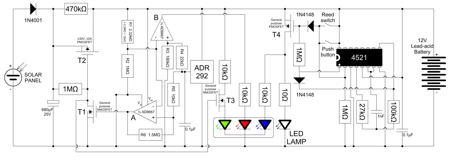
Fig 4. Simple solar PV charging of a lead-acid battery for a woodshed light
The comparator has 0V output when the battery voltage exceeds 13.8V, which turns off T1 and T2 and turns on T3 and the green LED in the tricolour indicator LED. With charge turned off, and the LED drawing 1mA, the battery voltage will gradually fall. The comparator changes state again when the battery voltage drops to 13.4V and turns the PMOS power switch back on, connecting the solar panel directly to the battery again, providing its output voltage is high enough. If the solar panel is unilluminated no current flows when T2 is turned on since the solar panel and the battery are isolated from each other by the 1N4001 diode.
If the solar panel is not producing power when the battery voltage drops below 13.4V it will continue to drift down, from self-discharge or from current drawn by the 4W white LED lamp. If it should fall as low as 12.1V the red warning LED in the tricolour indicator is illuminated by the comparator (without hysteresis) using op-amp B.
This simple system keeps its battery in a reasonable state of charge for its application - occasional LED lighting. The lighting control system uses a 4W LED lamp, cannibalised from a mains-powered GU10 spotlight whose power circuitry had failed. When the woodshed door is opened a reed relay turns on a 4060 CMOS timer which turns on the light, and then turns it off again when the door is closed or after about six minutes if the door is still open. If light is needed for more than six minutes there is a push-button to reset the timer.
The tricolour LED indicator shines blue to indicate the LED lamp is, or should be, on. Since the indicator LED is mounted outside the woodshed this blue LED indicates if the reed switch fails to turn off the lamp when the door is closed.
These domestic maker circuits are not particularly novel, but they do illustrate some uses of references and op-amps in simple analog control and measurement - and in particular highlight a problem with some types of precision voltage reference, and its solution. And they're real - I've built 'em both in the last couple of months and they are in daily use.
James Bryant
Calshot - England
4th July 2015
1 Application Specific Integrated Circuits.
2 Marketing speak - the competition's products have "bugs", ours have "features".
3 It is not good for secondary batteries to be discharged below their "fully discharged" voltage, and may do permanent damage.
4 Of course a higher supply voltage may be used - up to +14V - without risk of damage to the ADR91 or the AD822. With higher supplies the series resistor to the red LED should be increased to limit its supply current to 10mA, and using N-MOS devices with low thresholds is no longer necessary. The PMOS threshold is less important since its source is connected to the positive supply and its gate, when it is on, to the negative supply.
5 Or for $1 in a 99¢ Shop.
6 Caveat emptor - Latin - "Let the buyer beware!"
7 Usually when its snowing.